Introduction to the Physical Pendulum
Mount any rigid body such that it can swing in a vertical plane about an axis passing through the body. You have constructed what is known as a physical pendulum. The video below shows an example of such a pendulum. In this video, a rigid circular body is swinging about an axis very close to the edge of the circle. The circle was cut from a piece of cardboard. PocketLab Voyager is resting at the bottom of a ring stand directly below the pivot point of the pendulum. A tiny magnet has been attached to the bottom of the circle. You will notice that twice during each period, PocketLab records a spike in magnetic field intensity, when the magnet is closest to PocketLab. An analysis of these spikes over several periods yields an accurate determination of the physical pendulum's period of oscillation.
Physical Pendulum Theory
Figure 1 shows an irregular shaped object that pivots about a frictionless axis perpendicular to the plane of the figure at point P. The object is displaced from its equilibrium position by an angle θ. The equilibrium position is when the center of mass C of the object is directly below the pivot point. The distance between the pivot point and the center of mass is d. By considering the dynamics involved, the figure shows the derivation of an equation for the period T of the physical pendulum. Solving this equation for the moment of inertia I, the equation in the box at the bottom of the figure is obtained. The acceleration of gravity g is taken as a known quantity, and T, M, and d are all measurable. This equation, therefore, allow us to determine the moment of inertia of any object through any specific pivot point on that object! Note the assumption that θ is assumed to be small. If the angle of swing is kept to not more than about 30⁰, then θ and sin θ will differ by not more that about 4%. The calculation of I is a bit tedious when it needs to be repeated many times. Therefore, you may find it convenient to construct a spreadsheet to calculate I upon entering values for T, g, M, and d.
PocketLab's Role in This Lesson
There is a clear advantage to using PocketLab as described above in this lesson. PocketLab allows calculation of the period of the physical pendulum much more accurately than possible with a stop watch. The use of PocketLab for this purpose eliminates errors associated with reaction times in starting and stopping a stop watch. PocketLab should also be set to the highest data rate possible (50 points/second). Success in this lesson depends upon accurate measures of the period T of a physical pendulum. It is also advisable to measure pendulum mass with a balance capable of nearest 0.1 g, or even 0.01 if possible.
The Physical Pendulum Setup
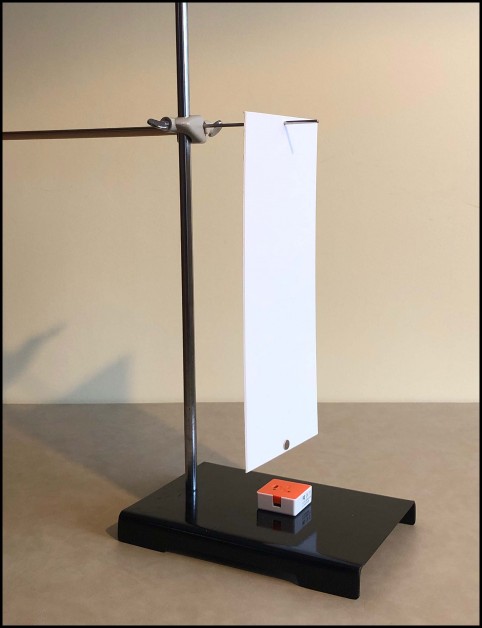
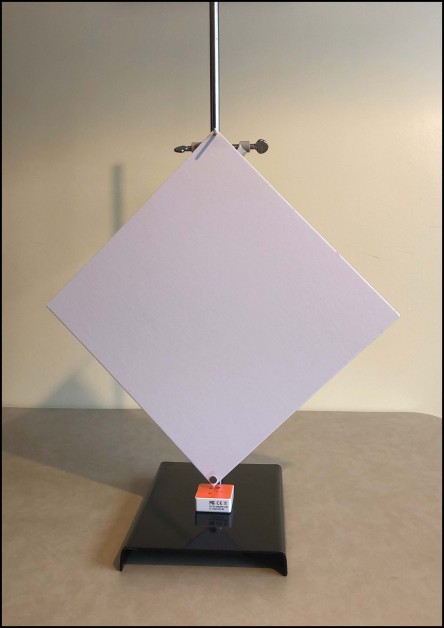
For clarity, Figure 2 shows an angled view of the apparatus. The physical pendulum, a cardboard rectangle, is suspended from a pivot point very close to the short edge of the rectangle. The pivot is a thin metal rod that has been clamped to a ring stand. A wood dowel rod (or something similar) is used as well, since the clamp screw does not screw tight enough to pinch the metal rod to the clamp. Students should wear safety goggles to prevent any possibility of being poked in the eye by the thin metal rod. PocketLab rests at the bottom of the ring stand. A tiny magnet has been taped to the center of the short bottom edge of the rectangle. PocketLab's magnetometer senses the magnetic field each time the magnet swings past PocketLab.
Definition of Moment of Inertia
The moment of inertia of an object rotating about a particular axis is somewhat analogous to the ordinary mass of the object. Moment of inertia can be defined by the equation
The moment of inertia is the sum of the masses of the particles making up the object multiplied by their respective distances squared from the axis of rotation. For continuous rigid objects, the equation would be similar but making use of integrals instead of a sum. It should be noted that by the definition, the moment of inertia of a body depends not only on the particular axis on which it rotates, but also on its shape and the way in which its mass is distributed. Calculation of these integrals can be very tedious. Therefore, in this lesson we will make use a table of moments of inertia so that we can concentrate on the physics and not worry about calculating what are often complex integrals.
Physical Pendulum Lesson Objectives
- In this lesson you will determine the moment of inertia for several common geometric cardboard shapes about a specific pivot point in each object. The objects will be physical pendulums that swing about a specified axis perpendicular to the plane of the shape. PocketLab will be used to measure the period for each pendulum.
- You will then compare your experimental moments of inertia to theoretical moments of inertia presented in Wikipedia's article "List of moments of inertia". Comparisons will be expressed as the percent difference between your experimental result and the theoretical moment of inertia, based upon a fraction of the theoretical moment of inertia. The percent difference would be negative in the event that your experimental result is less than the theoretical, and positive if the experimental result if greater than the theoretical. The shapes will be investigated in the order of complexity of the physics and mathematics involved. These shapes, in the order in which they are investigated, are as follows:
- Rectangle
- Circle
- Square
- Equilateral Triangle
- Finally, you will determine the moment of inertia about a specific axis of a general rectangle as well, an irregular curved shape, and an object with "negative space". No theoretical formulas are presented in the Wikipedia table for these shapes. Never the less, you can still determine these moments of inertia experimentally. Based upon the percent errors you obtained from the known shapes in objective 2, how confident are you in the moments of inertia of the general rectangle, the irregular curved shape, and the object with negative space?
Rectangle Investigation
Cut a rectangle from cardboard that is similar in size and shape as that shown in Figure 2. Experimentally determine its moment of inertia about the axis shown in Figure 2.
Scroll down the Wikipedia List of moments of inertia until you see the entry shown in Figure 3. This entry corresponds to the rectangle that you are currently investigating. Using the formula shown in Figure 3, determine the theoretical moment of inertial of your rectangle about the axis of rotation x. Compute the percent difference and record your results in the data table.
Circle Investigation
Cut a circle from cardboard that is similar in size to that shown in the embedded video. Experimentally determine its moment of inertia about the axis shown in the video.
Scroll down the Wikipedia List of moments of inertia until you see the entry shown in Figure 4. You are interested in the z moment of inertia. This gives you the moment of inertial of a circle that is rotating about its center of mass. But your circular cardboard is rotating about a point near the edge of the circle! As mentioned earlier, the moment of inertia depends on the particular axis of rotation. So ... how can we determine the moment of inertia when the circle rotates about a point near its edge?
As it turns out, there is a simple and extremely useful theorem, known as the Parallel-Axis Theorem, that expresses the relationship between the moment of inertia I of an object about any any axis and its moment of inertia with respect to a parallel axis through the center of mass. If Ic is the moment of inertia about the center of mass, m is the mass of the object, and w is the distance between the two axes, this theorem tells us that the moment of inertia I is given by the equation
Use the parallel axis theorem and the z entry in the Wikipedia table to determine an equation for the moment of inertia about a point near the edge of the circular plate. The equation you derive should agree with the Wikipedia entry shown in Figure 5.

Calculate the theoretical value for this moment of inertia and compare it to the value you obtained experimentally. Compute the percent difference and record your results in the data table.
Square Investigation
Cut a square from cardboard that is similar in size to that shown in Figure 6. Experimentally determine its moment of inertia about the axis shown in this figure, i.e., an axis that is very close to one of the vertices of the square.
Scroll down the Wikipedia List of moments of inertia until you see the entry shown in Figure 7.
- What is the value of n in the equation shown for your square?
- Obtain a formula for the moment of inertia about the center of mass (barycenter) in terms of m and R?
- Recast the equation in terms of m and a, where a is the length of each side of the square.
- Use the Parallel-Axis Theorem to determine an equation for the theoretical moment of inertia about a vertex of the square in term of m and a.
- Calculate the theoretical value for this moment of inertia and compare it to the value you obtained experimentally. Compute the percent difference and record your results in the data table.
Equilateral Triangle Investigation
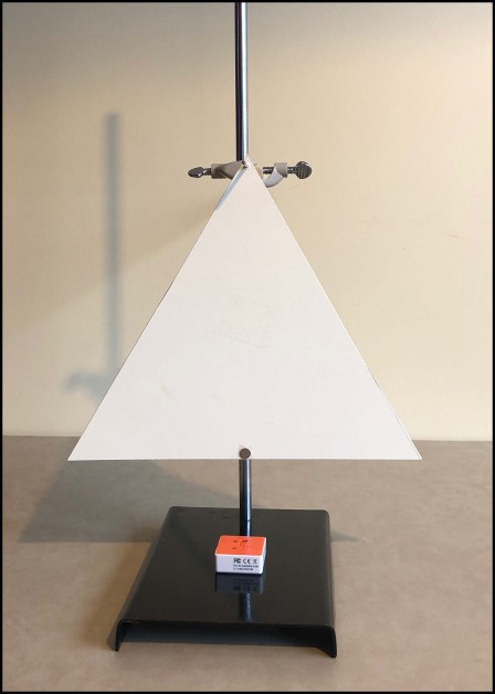
Cut an equilateral triangle from cardboard that is similar in size to that shown in Figure 8. Experimentally determine its moment of inertia about the axis shown in this figure, i.e., an axis that is very close to one of the vertices of the equilateral triangle.
The theoretical equation for the moment of inertia of an equilateral triangle about its center of mass follows from Figure 7 for a regular polygon.
- What is the value of n in the equation shown for your equilateral triangle?
- Obtain a formula for the moment of inertia about the center of mass in terms of m and R?
- Recast the equation in terms of m and a, where a is the length of each side of the equilateral triangle.
- Use the Parallel-Axis Theorem to determine an equation for the theoretical moment of inertia about a vertex of the equilateral triangle in term of m and a.
- Calculate the theoretical value for this moment of inertia and compare it to the value you obtained experimentally. Compute the percent difference and record your results in the data table.
General Triangle Investigation
There are no entries in the Wikipedia moments of inertia table for a general triangle. Therefore you will only be determining the moment of inertia of such a triangle experimentally. Cut a general triangle from cardboard that is similar in shape and size to that shown in Figure 9. A pivot point should be chosen near one of the three vertices.
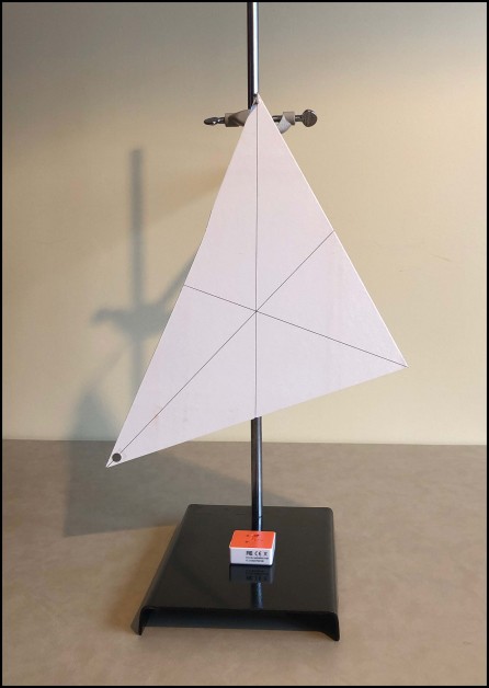
As usual, in order to use the equation for the moment of inertia shown in Figure 1, you need to know the distance d between the pivot point and the center of mass. This means that you need to know the location of the center of mass. To find the center of mass, you need only recall a basic theorem from geometry. This theorem states that the three medians of a triangle intersect at its centroid (center of mass). Each median is drawn from a vertex to the center of the opposite, as shown in Figure 9. It should not surprise you, then, that when the triangle is suspended from one of its vertices, the median lies vertically up and down. This is seen in Figure 9.
Record your experimental moment of inertia in the data table.
Irregular Curved Shape Investigation
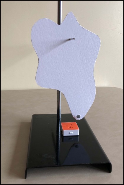
Cut an irregular curved shape from cardboard that is similar in size and shape to that shown in Figure 10. Determine the moment of this curved shape. It is rotating about an internal axis perpendicular to the shape. Record your experimental moment of inertia in the data table.
Object with "Negative Space" Investigation
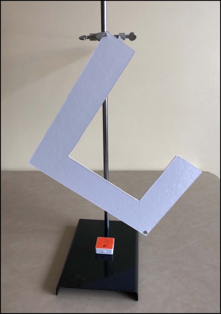
You might be wondering what is meant by the term negative space? According to an artist's definition, negative space can be thought of as the space between and around an object. Cut an object from cardboard that is similar in size and shape to that shown in Figure 11. Determine the moment of inertia of this curved shape. It is rotating about an axis near one of the vertices of the shape. Record your experimental moment of inertia in the data table.
Based upon the percent errors you obtained from the known shapes, how confident are you in the moments of inertia of the general rectangle, the irregular curved shape, and the object with negative space?
Data Table