Convert the PocketLab HotRod to an Inertia Cart
The PocketLab Inertia Cart
This cool inertia cart dates back to the early 1900's, but hasn't seen much action since, primarily due to a lack of ease in construction. However, now with the PocketLab HotRod and three 3D printable parts whose .STL files are included with this lesson, you can use this demonstration in your classroom. Depending upon the grade level of your students, you can customize the discussion as appropriate. Concepts involved include Newton's Laws of Motion, pulleys, force, acceleration, Half-Atwood machine, inertia, and moment of inertia.
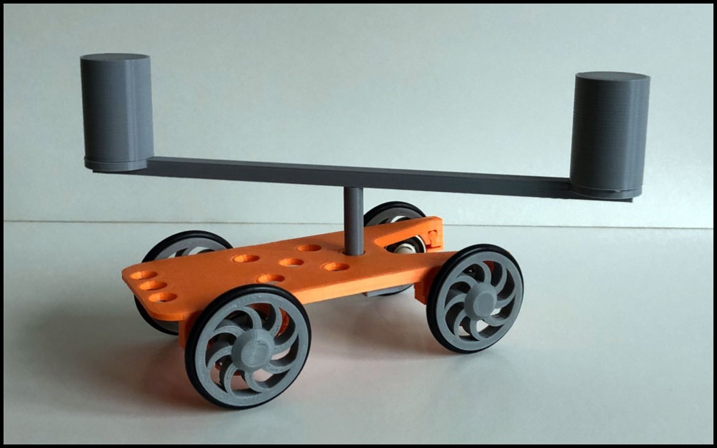
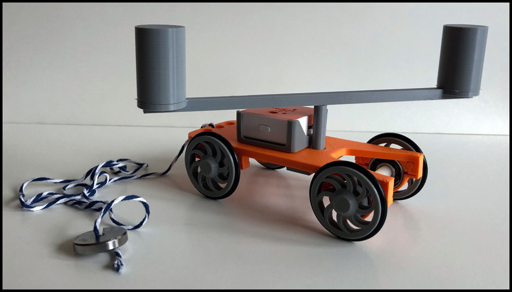
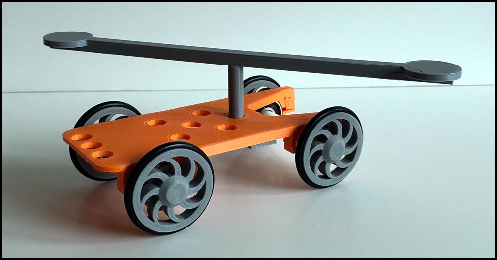
Figure 1 shows the complete PocketLab Inertia Cart. A horizontal bar is designed so that it can rotate freely about the vertical axis of a post that has been mounted to the PocketLab HotRod. Masses are attached to the extremities of this bar at equal distances from the pivot point. The masses are equal in volume, but one has a greater mass than the other. (One of the masses is 3D printed at 20% infill while the other is printed at 100% infill, thus equal in volume but different masses!) A string is attached to the cart on a table top. The cart is allowed to accelerate by a mass at the other end of the string which is hanging over a pulley, much like a Half-Atwood machine.
Action Videos of the PocketLab Inertia Cart
Two slo-mo videos, each about 10 seconds in length, of the PocketLab Inertia Cart in action were created. In the first video, shown below, equal masses were attached to the horizontal arm. The arm remains in the same position relative to the cart during the entire period of acceleration, even after impacting the white barrier on the far right.
In the second slo-mo video, shown below, different masses were attached to the horizontal arm. While accelerating, the greater mass lags behind. But when the cart impacts the barrier, the greater mass does the reverse.
The final video, shown below, was created with the PocketLab app. It is not slo-mo and is a combined data and video view when releasing the PocketLab Inertia Cart with different masses on the horizontal bar. A graph of x-acceleration versus time is overlaid on the video.
Assembling the PocketLab Inertia Cart
The first step is to 3D print the five objects shown in Figure 2. The .STL files are included with this lesson. Part (a) is the pivot support post, part (b) is the horizontal arm, and parts (c) are the masses, all the same size. Two masses are printed at 20% infill, and one mass is printed at 100% infill.
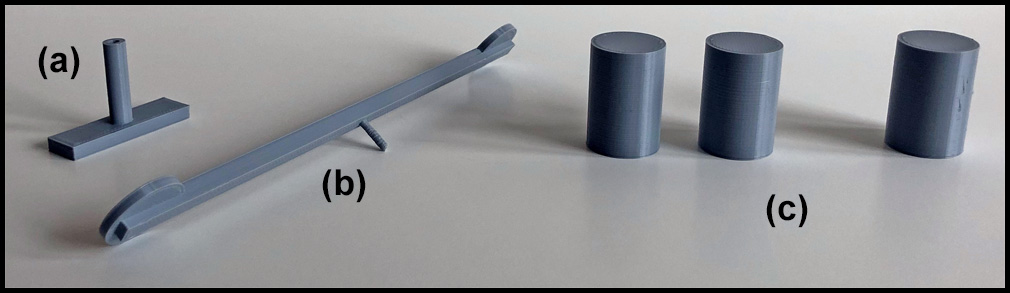
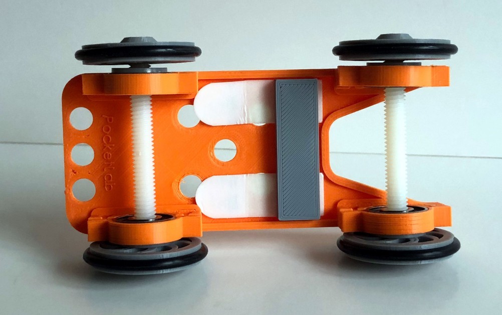
Figure 3 shows the pivot post after it has been mounted to the PocketLab HotRod.
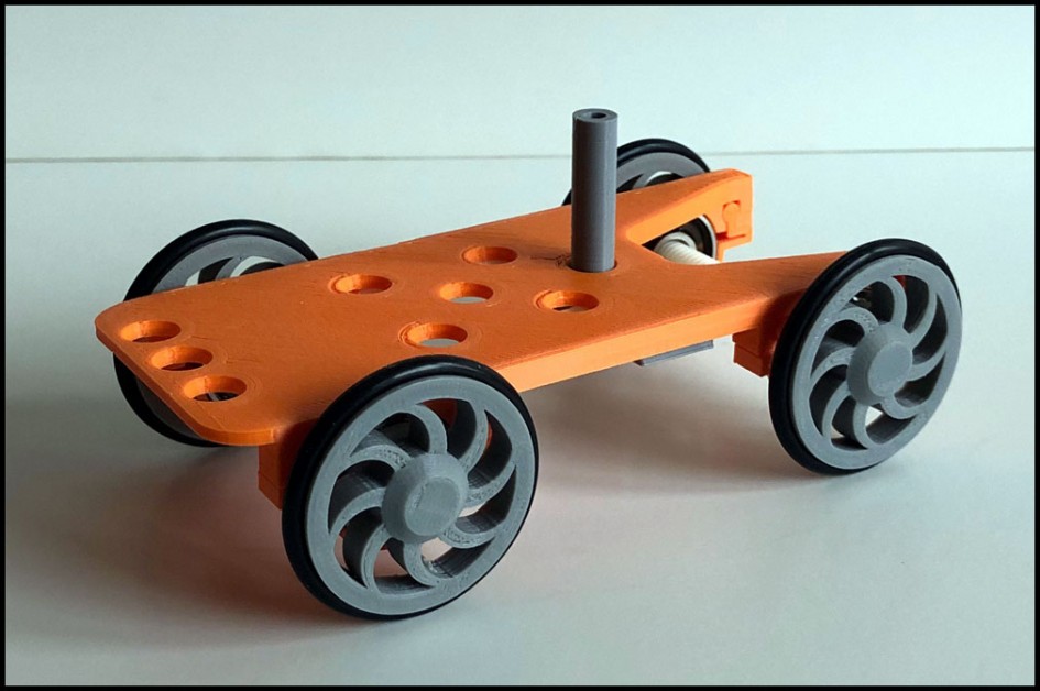
Figure 4 shows that the pivot post has been mounted to the underside of PocketLab with damage-free hanging strips. They provide for a strong solidly mounted pivot post.
The horizontal arm is inserted into the pivot post.
The masses are attached to the horizontal arm with double-stick tape.