PocketLab University
PocketLab University is an initiative to develop college-level labs that students can conduct at home, in their dorm room, or in any other setting without the need for laboratory equipment. Lab 1 uses PocketLab Voyager to understand the physical principles that enable temperature sensors to convert the physical property of temperature to an electrical property that we can measure with simple circuitry. The student assignment is below. If you are an instructor or professor and you would like to access the instructor guide, please contact us at [email protected].

The Physical Principles of Measuring Temperature
For our first exercise with the PocketLab we’re going to explore how to take a raw parameter from a transducer and make it a useable signal. We will also look at some of the non-idealities that we have to face when working with real sensors. We will do this by looking at the temperature sensitivity of three basic electronic components: a standard 10 kΩ carbon-film resistor; a thermistor; and a diode.
Materials
- Your PocketLab (including the external temperature probe)
- A device running the PocketLab app to record the data
- A way to make cold (<50° F) and hot (>150° F) water (e.g. ice cubes and a microwave).
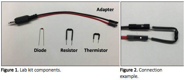
- The items in your lab kit
- Temperature port adapter
- Resistor
- Thermistor
- Diode
Procedural Tips
- You might notice that for some experiments the ADC output will change relatively little (~50 counts at most), and for some it will change hardly at all. This is normal.
- Don’t submerge the resistor or thermistor past the black heat-shrink. Tap water conducts electricity quite well and will act as a parallel resistor if any of the exposed metal is submerged. This isn’t an issue for the diode.
- The diode is polarity sensitive. At room temperature it should give a value of ~150 counts on the ADC. If it’s much higher try reversing the direction.
- The diode might be somewhat loose when inserted into the sockets of the adapter. Try to make sure you get a good connection. You might have to bend the leads slightly to make it a bit more snug.
Part 1: Preliminary Questions
Throughout this exercise we will be using the external temperature probe input on the PocketLab to measure voltage or resistance. The probe itself is a thermistor, and the PocketLab is setup to measure its resistance using the circuit in figure 3 below. The ADC value reported in the app is the output of the ADC in counts. The ADC has a resolution of 10 bits and a reference voltage (Vin) of 3.0 V and Rref is 10 kΩ.
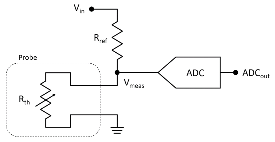
- What is Vmeas as a function of ADCout?
- What is Rth as a function of ADCout?
Part 2: Constructing Calibration Curves
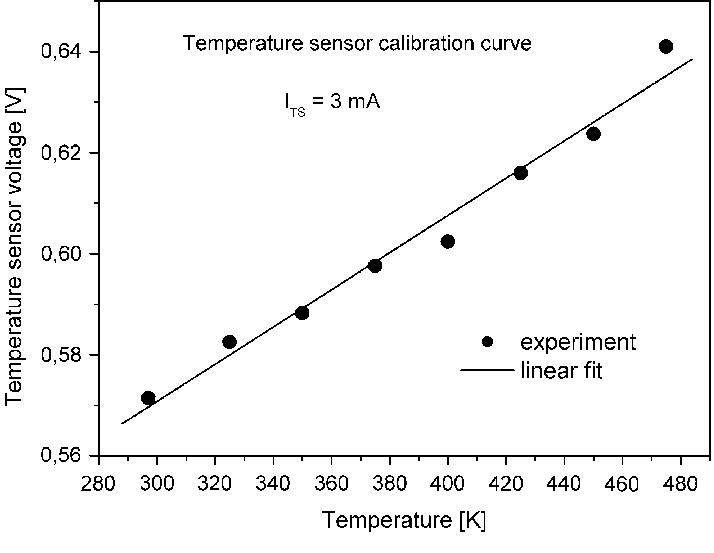
Many sensors now directly output a calibrated digital value of the parameter measured, but at some point they must do a conversion to generate that value. This requires knowledge of the transducer response. We’re going to investigate that here. For this part, you should just eyeball the data reported on the app; no need to make a recording.
https://www.researchgate.net/figure/Temperature-sensor-calibration-curve_fig4_225597738
Procedure
- Prepare a glass of cold water. The exact temperature isn’t important, just make sure it’s fairly cold (<50° F).
- Measure the temperature of the water using the external temperature probe. Hold the tip of the probe in the middle of the glass about 0.5 in below the surface. Wait until the temperature appears to stop changing and write down the reported value.
- Connect the thermistor (the one with short leads) in your lab kit to the PocketLab, select “ADC” in the app, place the tip in the water, wait for the measurement to stabilize, and write down the reported ADC value. Repeat this step for the resistor and diode. Try to do this quickly, before the temperature of the water changes significantly.
- Prepare progressively warmer samples of water (we want at least five different temperatures spanning from <50° F to >150° F). Repeat steps 2 and 3 for each sample. Remember to test all three components for each sample.
- Use the data you just recorded to answer the following questions.
Questions
- Provide calibration curves for each of the three components. The data should be plotted as either resistance or voltage depending on the component.
- What is the sensitivity of each of the three components? How are you specifying sensitivity?
- What is the nonlinearity of the thermistor? How are you specifying nonlinearity?
Part 3: Measuring Transducer Dynamics
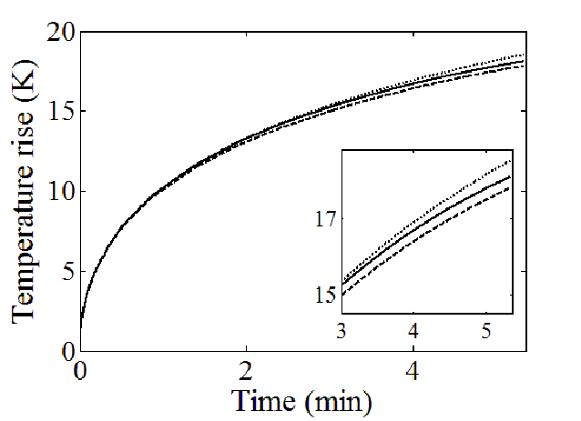
As we discussed in lecture, sensors take time to adjust to what they are measuring. This is captured in the rise time parameter. In this part we’re going to measure the rise time of the thermistor (you don’t need to do this part for the other two components).
Procedure
- Prepare a glass of hot water.
- Measure the temperature of the water using the external temperature probe.
- Connect the thermistor in your lab kit to the PocketLab. In the app, select the temperature probe and set the recording rate to 50 samples per second.
- Start recording data in the app and then place the tip of the thermistor in the water. Place it in in one smooth and rapid motion. Be careful not to go too far and submerge any exposed metal. Hold it still in the water for 20 s.
- Remove the thermistor, stop recording, and export the data.
- Use the data you just recorded to answer the following questions.
Questions
- Provide a plot of the time series data from the thermistor. (This won’t show the right y-axis values, but we only care about the dynamics.)
- What is the 63% rise time of the thermistor for the experiment we just did?
- Measure and report the response time for one other test condition. Specify the test condition. Why is this number different?
Analysis
Temperature sensors are among the slowest sensors in wide use. This is because they have a large thermal mass relative to the thermal resistance separating them from their surroundings. Fortunately, for similar reasons, most macro-scale systems don’t change temperature very quickly. This highlights an important point: the dynamics of a sensor are judged relative to the dynamics of the system to be measured. A slow system needs only a slow sensor.
Authors
This activity was developed and written by Seth Cordts, Daniel Heywood, Ananth Yalamarthy, and Clifton Roozeboom
