Introduction
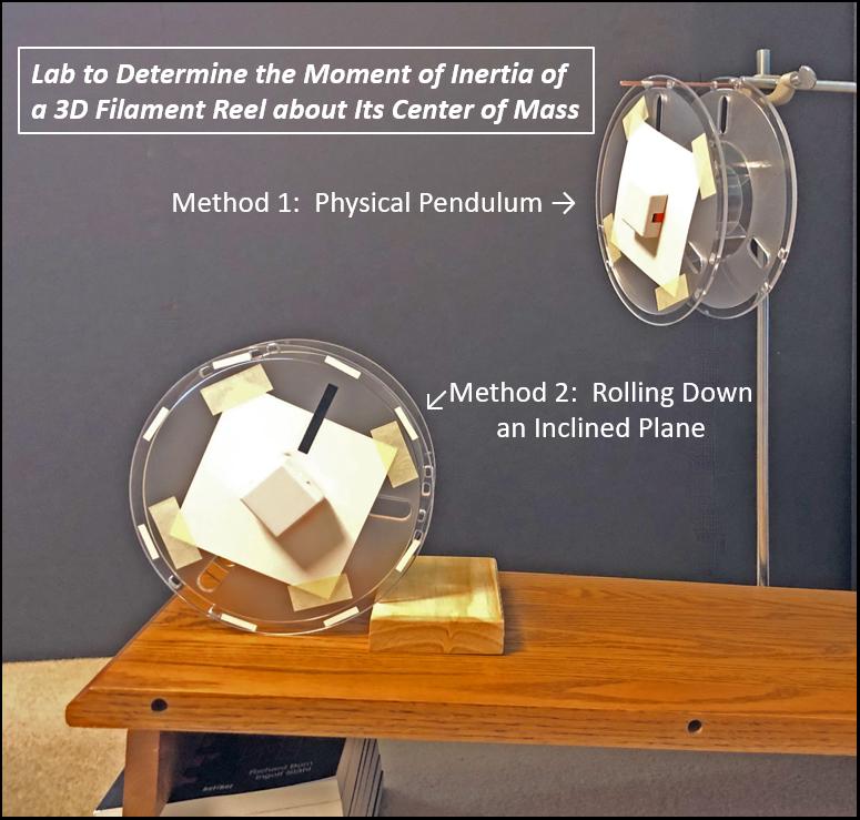
Your school can put all of those empty 3D filament reels to good use in the physics classroom. There's a good chance that you and your students could come up with some interesting physics lab investigations using these reels. As shown in Figure 1, attach Voyager or PocketLab One to the reel, and the possibilities are endless! This lesson describes a lab in which your students determine the moment of inertia of an empty 3D filament reel about its center-of-mass. They will accomplish this using two independent methods. One method has the reel acting as a physical pendulum, while the other method has the reel rolling down an inclined plane. There is a lot of great rotational kinematics and dynamics here, so let's get started!

The "Physical Pendulum" Method for Determining the Moment of Inertia About the Center-of-Mass
Video
Mount any rigid body such that it can swing in a vertical plane about an axis passing through the body. You have constructed what is known as a physical pendulum. The setup for our empty 3D filament reel can be seen in the short video below. The reel is swinging from a thin metal rod about an axis very close to the reel's edge. (The reel used by the author was an empty 1-kg PolyLite™ reel from polymaker. Conveniently, there are small holes very near the edge of the reel.) The PocketLab app collects angular velocity data from Voyager at the rate of 50 points/second. The time between adjacent peaks in angular velocity represents the period of this physical pendulum. An analysis over several periods yields an accurate determination of the physical pendulum's period of oscillation T.
Physical Pendulum Theory
Figure 2 shows an irregular shaped object that pivots about a frictionless axis perpendicular to the plane of the figure at point P. The object is displaced from its equilibrium position by an angle θ. The equilibrium position is when the center of mass C of the object is directly below the pivot point. The distance between the pivot point and the center of mass is d. By considering the dynamics involved, the figure shows the derivation of an equation for the period T of the physical pendulum. Solving this equation for the moment of inertia I, the equation in the box at the bottom of the figure is obtained. The acceleration of gravity g is taken as a known quantity, and T, M, and d are all measurable. This equation, therefore, allows us to determine the moment of inertia of any object through any specific pivot point on that object! Note the assumption that θ is assumed to be small. If the angle of swing is kept to not more than about 30⁰, then θ and sin θ will differ by not more that about 4%. The calculation of I is a bit tedious when it needs to be repeated many times. Therefore, you may find it convenient to construct a spreadsheet to calculate I upon entering values for T, g, M, and d.
The Parallel Axis Theorem
The equation for I in Figure 1 gives the moment of inertia through an arbitrary point P that is displaced a distance d from the center-of-mass. But what we want is the moment of inertial about the center-of-mass. It won't work if we used the center-of-mass as the pivot point, as the object would not oscillate in this case.
As it turns out, there is a simple and extremely useful theorem, known as the Parallel-Axis Theorem, that expresses the relationship between the moment of inertia I of an object about any any axis and its moment of inertia with respect to a parallel axis through the center of mass. If Ic is the moment of inertia about the center of mass, m is the mass of the object, and w is the distance between the two axes, this theorem tells us that the moment of inertia I is given by the equation
Results
In a trial done by the author, the following results were obtained. The period T = 0.756 s, M = 0.256 kg, d = 0.099 m, and the value of 9.81 m/s/s was used for g. The resulting value for the moment of inertia I about point P was 0.00360 kg*m*m. Then, using the parallel axis theorem, the moment of inertia about the center-of-mass, Ic, was 0.0012 kg*m*m. (Note that w = d = 0.099 m.)
It should also be noted that with Voyager attached to the reel, we actually determined the moment of inertia of [voyager + reel], and not the reel alone. However, with the reel having a mass of 239 g, and Voyager having a mass of only 17 g, the effect of Voyager on the moment of inertia was probably minimal.
The "Rolling Down an Incline" Method for Determining the Moment of Inertia About the Center-of-Mass
Video
The setup for our empty 3D filament reel can be seen in the short 3-second video below. Books can be used to prop the inclined plane to any desired angle. The angle can be determined by geometry, or directy by a cell-phone app that measures tilt to the nearest 1/10 of a degree. The PocketLab app records angular velocity of the reel as it rolls down the incline. The slope of the angular velocity graph tells us the angular acceleration. As you will see, both the angle of incline and the angular acceleration, among other parameters, are needed to determine the moment of inertia about the reel's center-of-mass.
"Rolling Down an Incline" Theory
Figure 3 shows a free-body diagram of an object rolling down an inclined plane. Also included in the figure is a concise explanation of the physics involved. Since we are interested in knowing the moment of inertia, the figure shows how to derive an equation for I about the center of mass. The acceleration of gravity g can be taken as a known quantity, and M, R, θ, and α are all measurable. The calculation of I is a bit tedious when it needs to be repeated many times. Therefore, you may find it convenient to construct a spreadsheet to calculate I upon entering values for g, M, R, θ, and α
Results
Figure 4 shows a table of results obtained by the author for inclines θ ranging from 3.6⁰ to 18.4⁰. The values for the angular acceleration were obtained from the slope of Voyager's angular velocity versus time graphs, and then converting from deg/s/s to rad/s/s. The corresponding values of the moment of inertia I of the empty 3D filament reel average out at about 0.00135 kg*m*m. This is in good agreement with the value 0.0012 kg*m*m obtained earlier by the physical pendulum method!
Suggested Lab Procedures
The teacher might consider assigning the "physical pendulum" method to half of the student lab groups and the "rolling down an incline" method to the other half. For the groups doing the "rolling down an incline" method, the teacher could further assign different angles of the inclined plane for each group. The moment of inertia for each group could be posted on a whiteboard followed by a class discussion of the results.
- Do both methods provide similar values for the moments of inertia of the reels?
- Do the resultant values for the moments of inertia for the "rolling down an incline" method appear to be independent of the angle of the incline?
- What are some possible causes for error in this experiment?
- Why would it be difficult to determine the theoretical value of the moment of inertia of the empty 3D filament reel by use of the basic definition of moment of inertia:
Additional Labs Making Use of Empty 3D Filament Reels