

Introduction to Rangefinders
Rangefinders, sometimes called motion sensors or motion detectors are commonly used in probeware, camera autofocus, and robotics. Rangefinders operate on the principle of a time-of-flight measurement and consist of a transmitter and receiver. The transmitter emits a signal (ultrasonic or optical) then the receiver detects the reflection or echo of the signal. The amount of time between transmit and receive is called the time-of-flight and is used to calculate the distance to the reflecting object:
Distance = (time of flight) / (2 x speed of signal)
The principle of operation is simple, but the design of the sensors is complex. This article will explain:
- Operating principles of infrared and ultrasonic rangefinder sensors
- Commercial examples of rangefinder components
- Rangefinder applications
- Science activities to do with a rangefinder
You can investigate rangefinder concepts more in depth with:
- The PocketLab Voyager which contains an optical rangefinder, the ST VL53L0X
- Ultrasonic rangefinder components like this from Sparkfun
- Ultrasonic rangefinders in the PASCO Wireless Motion Sensor, or the Vernier Go Direct Motion Detector
Operating Principle - Ultrasonic
Human ears can hear pressure waves in the frequency range of 20 Hz to 20 kHz, which we call sound. Ultrasound is a term for pressure waves above the audible frequency, and ultrasonic rangefinders often operate in the 50 kHz frequency. An ultrasonic rangefinder contains a transmitter which emits a short signal called a chirp. The chirp transmits through the air in a radial pattern from the transmitter at the speed of sound, which is about 343 m/s = 767 mph = 1125 ft/s. The speed of sound varies slightly with the humidity, temperature, and pressure of the air.
The signal strength of the chirp decreases by 1/(distance^2) as it moves away from the transmitter radially. When the chirp hits an object the pressure wave does three things:
- Part of the wave is reflected back to the source as an echo
- Part of the wave is deflected in a different direction
- Part of the wave is absorbed and transmitted into the object
The echo that returns to the sensor detector is the part of the signal that can be used for measurement. If you know the time the chirp was transmitted and the time the echo was received, you can use the simple equation:
Distance = (time of flight) / (2 x speed of signal)
to calculate the distance to the reflecting object. The accuracy of measurement is dependent on how accurate the timing is and reducing error from multiple reflections or external noise.
Operating Principle - Optical
An optical rangefinder operates in mostly the same way as an ultrasonic rangefinder but it emits and receives optical signals. The sensor transmitter sends out a pulse of optical signals, the receiver measures the reflected radiation, and the internal clock measures the time differences. However, for optical rangefinders, the timing requirement is much much faster. The speed of light in a vacuum is 3x10⁸ m/s, which is about 1,000,000 times faster than the speed of sound, therefore the timing requirements are 1,000,000 times faster for comparable positional resolution. Some optical rangefinders can measure 1 cm of distance change which equals just 67 picoseconds for the light to travel to and from the object.
Commercial Examples of Optical Rangefinders
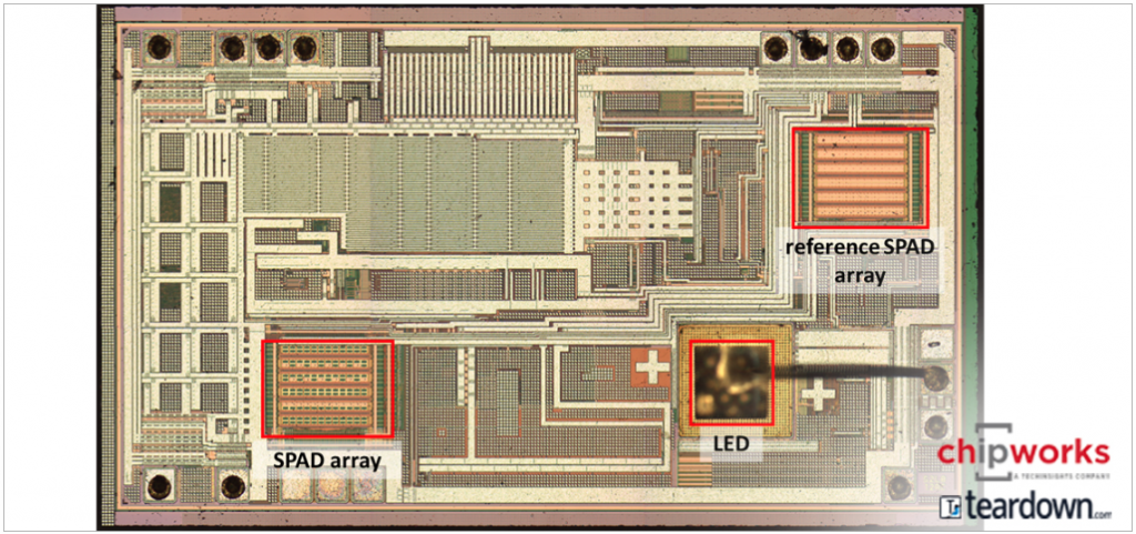
STMicroelectronics has a family of time-of-flight rangefinders used for proximity sensing: VL53L0X, VL53L1X, and VL6180X. These sensors operate in the infrared spectrum at 940 nm wavelength. The emitter is a vertical cavity self-emitting laser (VCSEL) and the detector is a single photon avalanche diode (SPAD) and these parts are integrated into system with timing and processing on board. The SPAD can count single photons hitting the detector and use this signal to measure the time-of-flight of the photons to the target and back. In the photos below you can see what the silicon chip looks like in the VL53L0X. The chip has two SPADs, one to measure the reflected signal and one that is covered up by the package and used as a reference to correct and calibrate the sensor.
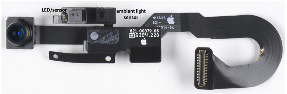
These rangefinders are used most widely in smartphones and cameras for autofocus and also for proximity recognition if you swipe your hand in front of a device like a paper towel dispenser. The PocketLab Voyager uses the VL53L0X to measure range from 10 cm to 2 m for hundreds of science and engineering applications. Optical rangefinders based on time-of-flight measurements are new technology, although sensors based on the intensity of reflected light have been in the market for many years.
Commercial Examples of Ultrasonic Rangefinders
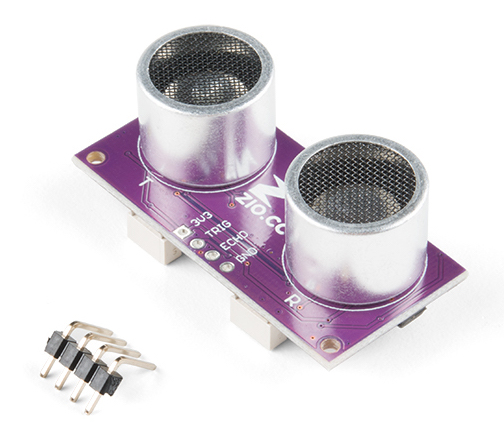
If you’ve done robotics or put together maker projects, you have probably seen an ultrasonic rangefinder. It looks like two metal bug eyes, with one metal cylinder the emitter and the other the receiver. Ultrasonic rangefinders were used in Polaroid cameras going back to the 1980s. Those sensors used a single transducer design with just one element that acted as the emitter and receiver.
Applications
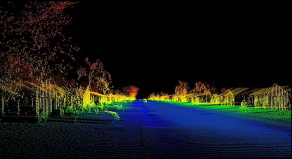
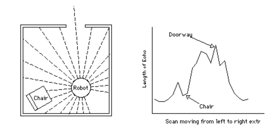
Rangefinders are similar in principle to LIDAR technology that is used in autonomous driving and other mapping applications. You can imagine putting a rangefinder on a rotating platform and being able to measure distances to objects in the line-of-sight and assembling a 2D map from the range data.
The lesson photo on top of this page is a LIDAR image from the music video for "House of Cards" by Radiohead. Instead of using cameras, the band used 3D renderings from LIDAR data which gives the video a unique style.
Science Activities using Rangefinders
